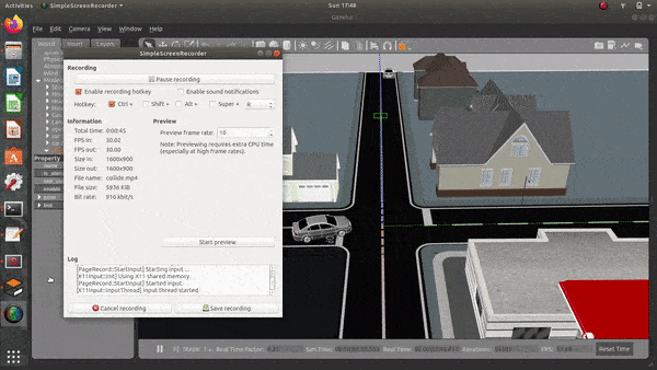
Road Junction
Goal
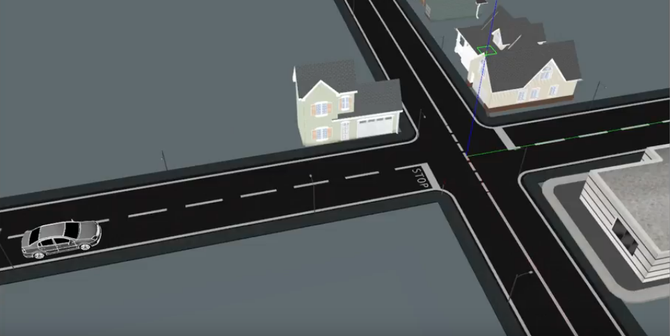
The goal of this practice is to implement the logic of a navigation algorithm for an automated vehicle. The vehicle must Stop at the T joint, where there is a stop sign, wait until there are no cars and pass once the road is clear.
Frequency API
Python
import Frequency- to import the Frequency library class. This class contains the tick function to regulate the execution rate.Frequency.tick(ideal_rate)- regulates the execution rate to the number of Hz specified. Defaults to 50 Hz.
C++
#include "Frequency.hpp"- to import the Frequency library class. This class contains the tick function to regulate the execution rate.Frequency freq = Frequency();- to instanciate the Frequency class.freq.tick(ideal_rate);- regulates the execution rate to the number of Hz specified. Defaults to 50 Hz.
Robot API
This exercise now supports ROS 2-direct implementation in addition to the original HAL-based approach. Below you’ll find the details for both options.
HAL-based Implementation
Python
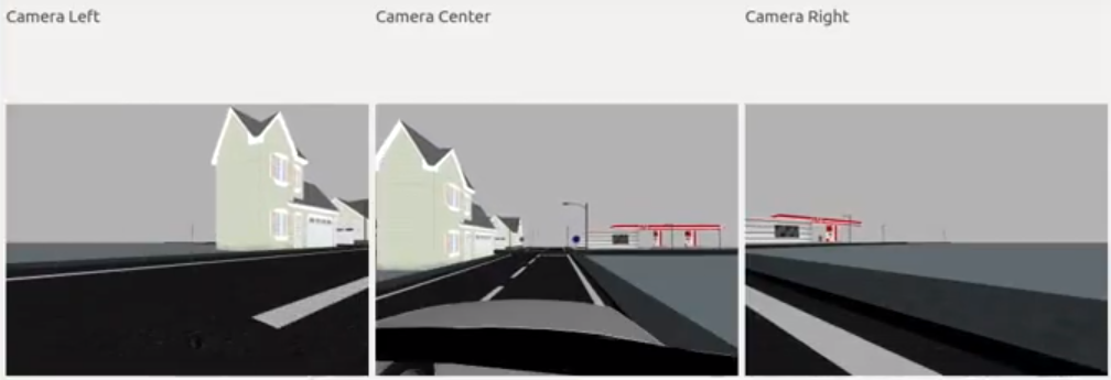
import HAL- to import the HAL (Hardware Abstraction Layer) library class. This class contains the functions that send and receive information to and from the Hardware (Gazebo).import WebGUI- to import the WebGUI (Web Graphical User Interface) library class. This class contains the functions used to view the debugging information, like image widgets.HAL.getImage()- to get the image (BGR8).HAL.getPose3d().x- to get the X coordinate of the robot.HAL.getPose3d().y- to get the Y coordinate of the robot.HAL.getPose3d().yaw- to get the orientation of the robot.HAL.setV(velocity)- to set the linear speed.HAL.setW(velocity)- to set the angular velocity.WebGUI.showImage(image)- allows you to view a debug image or with relevant information.
C++
#include "HAL.hpp"- to import the HAL (Hardware Abstraction Layer) library class. This class contains the functions that send and receive information to and from the Hardware (Gazebo).#include "WebGUI.hpp"- to import the WebGUI (Web Graphical User Interface) library class. This class contains the functions used to view the debugging information, like image widgets.HAL::get_image();- to get the image (cv::Mat).HAL::get_pose3d();- Returns the current pose as aHAL::Pose3dstruct with fieldsx,y(in m) andyaw(in rad).HAL::set_v(velocity);- to set the linear speed.HAL::set_w(velocity);- to set the angular velocity.WebGUI::show_image(image);- allows you to view a debug image (cv::Mat) or with relevant information.
In order to use the HAL-based controls you must include the following lines:
#include "HAL.hpp"
#include "WebGUI.hpp"
#include "Frequency.hpp"

void exercise() {
    Frequency freq = Frequency();
    // Enter sequential code!

    while (true)
    {
        // Enter iterative code!
        freq.tick();


    }
}
ROS 2-direct Implementation
Use standard ROS 2 topics for direct communication with the simulation.
-
/prius_autoparking/image_raw- Subscribe to this topic to receive the camera image.
Message type:sensor_msgs/msg/Image -
/cmd_vel- Publish to this topic to set both linear and angular velocities.
Message type:geometry_msgs/msg/Twist -
/odom- Subscribe to this topic to receive the car odometry.
Message type:nav_msgs/msg/Odometry
For image debugging:
/webgui/image- Publish to this topic to display a debug image in the WebGUI.
Message type:sensor_msgs/msg/Image
QoS:TRANSIENT_LOCAL
Python
Note: Ensure this import is included in your script to access the Web GUI functionalities.
import WebGUI - to enable the Web GUI for visualizing camera images.
To have frequency control you need to use standard ROS 2 mechanisms to manage loop timing:
rclpy.spin()- Event-driven execution using callbacks.rclpy.spin_once()- Single-step processing, often with custom timers.rclpy.Rate()- Loop-based frequency control.
Note
WebGUI already initializes rclpy internally, so this should be taken into account when building a direct ROS 2 solution.
C++
In order to use direct ros controls you must include the following lines:
#ifndef USER_NODE
#define USER_NODE

#include "rclcpp/rclcpp.hpp"

class UserNode : public rclcpp::Node {
  // Your class
};

#endif
You must define USER_NODE and a UserNode node class.
To have frequency control you may use a timer and a control function as follows:
  UserNode() : Node("user_node")
  {
    // More subscribers and publishers
    timer_ = create_wall_timer(100ms, std::bind(&UserNode::control_cycle, this));
  };

// More Code

  void control_cycle(){
    // Your function
  };
Videos
Theory
This exercise mostly revolves around simple Computer Vision and Control mechanisms. Let’s start with the Computer Vision tasks:
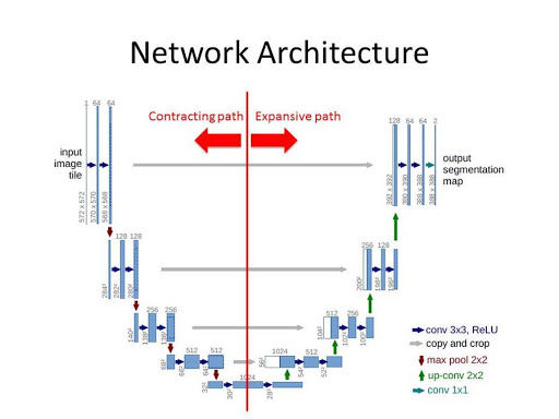
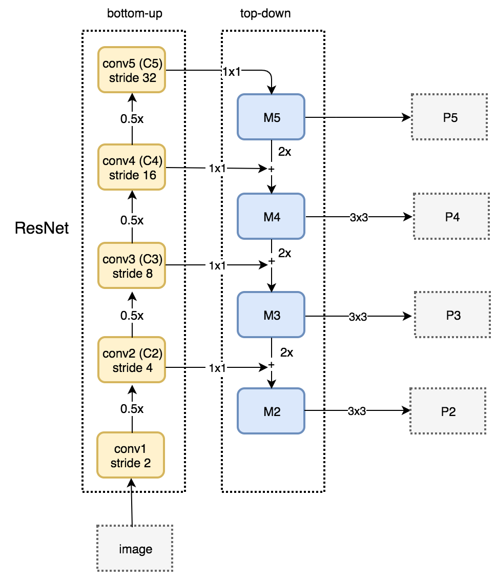
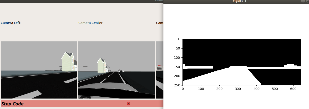
Image Segmentation
Image Segmentation is the process of partitioning a digital image into multiple segments. Segmentation is carried out to simplify the representation of information we receive from an input image. There are many ways to carry out image segmentation, but it all depends on the task at hand.
For extremely cluttered images, segmentation is carried out by the use of Convolutional Neural Networks. Some of the most useful Neural Networks developed for this task are: UNet, FPN and R-CNNs.
Some simpler methods involve the use of Clustering Algorithms like K-Means Clustering. The simplest of all methods is the use of Color Filters.
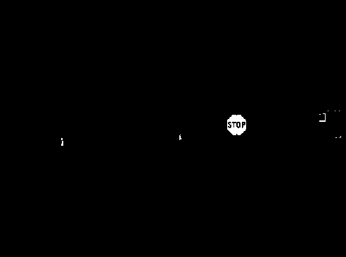
Color Filters involve the use of color spaces and their intensity values. By thresholding the input image by appropriate intensity values, we segment a specific color part of an image. For example, the Stop Sign in the exercise is a very specific red color which can be easily segmented. For more information about this topic, the Robotics Academy already has an exercise based on Color Filter.
Motion Detection
Motion detection is the process of detecting a change in the position of an object relative to its surroundings or a change in the surroundings relative to an object. Difference of Frames is the simplest of all motion detection algorithms. By taking the difference between the frame of reference and the current frame, motion can be very easily detected.
Control
We require the use of control mechanisms in order to make the Car follow the road and take turns.
PID is an excellent control algorithm which works by calculating the error and making adjustments to keep the error as minimum as possible. A very simple example would be, in case of a quadcopter that is required to maintain a particular height: If the height of the quadcopter is extremely far away from the required height(very high or very low), the quadcopter has to make large adjustments in it’s rotor speed. If the height is near the required value, the quadcopter has to make small adjustments. This video illustrates the concept very well.
Follow Line is an exercise based completely on the concept of PID.
The physical equation concerning rotational kinematics is v = ωr . This equation governs the relation between the radius of curvature, the magnitude of velocity and the magnitude of angular velocity. In order to increase the radius of curvature, we need to increase the velocity and decrease the magnitude of angular velocity. In order to decrease the radius of curvature, we need to decrease the velocity and increase the magnitude of angular velocity. This is the fundamental equation that allows our autonomous car to take effective turns.
Hints
Simple hints provided to help you solve the car_junction exercise.
Following the Road
Color Segmentation is the way to go to detect roads. Thresholding and then applying morphological operations can easily help us detect the roads in the image. The centroid of the generated binary blob can be easily followed by the car. However, there are tiny problems with this approach that can be addressed by using tricks(which the reader is expected to figure out on his/her own).
A really interesting implementation would be, by means of lane detection. Here is a really good implementation. But again, there are some problems in this approach as well. (Do make a video and share with us in case someone solves using this)
Stop Sign
The stop sign is of a very particular red color, which clearly stands out in the whole gazebo simulation. So, color filters are the best way to approach. Check out this video for more details.
Turning
Turning is a challenging part of this exercise. The parameters have to be tuned in a specific way to carry out the turn, and then the control should be passed to the follow road method in order to continue with the task. The physical equation given above can simplify the process of setting the parameters.
Illustrations
Contributors
- Contributors: Irene Lope, Alberto Martín, Francisco Rivas, Francisco Pérez, Jose María Cañas, Nacho Arranz.
- Maintained by Jessica Fernández, Vanessa Fernández.
References
- https://www.electrical4u.com/control-system-closed-loop-open-loop-control-system/
- https://en.wikipedia.org/wiki/PID_controller
- https://www.elprocus.com/the-working-of-a-pid-controller/
- https://www.tutorialspoint.com/control_systems/control_systems_introduction.htm
- https://instrumentationtools.com/open-loop-and-closed-animation-loop/
- https://trinirobotics.com/2019/03/26/arduino-uno-robotics-part-2-pid-control/
- http://homepages.math.uic.edu/~kauffman/DCalc.pdf