Follow Person RR
Goal
The objective of this practice is to implement the logic of a navigation algorithm that will be used to follow a person in a hospital using a R-CNN (Region based Convolutional Neural Network) called SSD (Single Shot Detector)
Simulated Turtlebot 2 (ROS Humble)
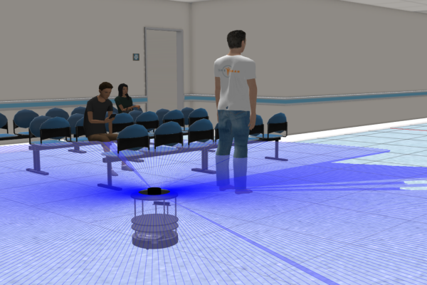
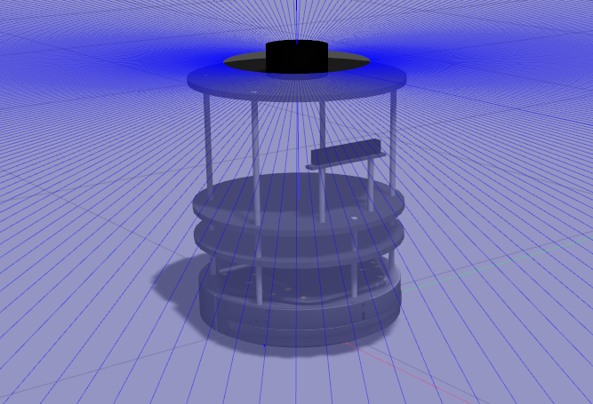
The robot that we will use is a Turtlebot2 (a circular mobile robot) implemented and developed for ROS Foxy and ROS 2 Humble. It has a RGBD camera so that we can detect objects or people, and it has a laser 360º for implement algorithms as VFF if you need to avoid obstacles.
Person model teleoperation mode
The web template includes a teleoperation mode that allows you to control a person within the hospital. To enable this, switch to the “Follow Person Teleop” universe and then you will can use the WASD keys to move the model.
- W: forward movement
- S: backward movement
- A: left rotation
- D: right rotation
If it doesn’t react, click on the area where the image is shown and try again.
Frequency API
Python
import Frequency- to import the Frequency library class. This class contains the tick function to regulate the execution rate.Frequency.tick(ideal_rate)- regulates the execution rate to the number of Hz specified. Defaults to 50 Hz.
C++
#include "Frequency.hpp"- to import the Frequency library class. This class contains the tick function to regulate the execution rate.Frequency freq = Frequency();- to instanciate the Frequency class.freq.tick(ideal_rate);- regulates the execution rate to the number of Hz specified. Defaults to 50 Hz.
Robot API
This exercise now supports ROS 2-native implementation in addition to the original HAL-based approach. Below you’ll find the details for both options.
HAL-based Implementation
Python
import HAL- to import the HAL(Hardware Abstraction Layer) library class. This class contains the functions that sends and receives information to and from the Hardware(Gazebo).import WebGUI- to import the WebGUI (Web Graphical User Interface) library class. This class contains the functions used to view the debugging information, like image widgets. Only for Gazebo Classic universes (the ones that do not say Harmonic at the end)import WebGUI2- to import the WebGUI (Web Graphical User Interface) library class. This class contains the functions used to view the debugging information, like image widgets. Only for Gazebo Harmonic universes.HAL.getImage()- to obtain the current frame of the camera robot.HAL.getPose3d().x- to get the position of the robot (x coordinate)HAL.getPose3d().y- to obtain the position of the robot (y coordinate)HAL.getPose3d().yaw- to get the orientation of the robot with regarding the mapHAL.getLaserData()- it allows to obtain the data of the laser sensor. It returns a list of 180 laser measurements (0 - 180 degrees)HAL.setV()- to set the linear speedHAL.setW()- to set the angular velocityHAL.getBoundingBoxes()- this method calls a detect() neural network’s method to obtain a list of detected objets from an image passed as argument.WebGUI.showImage()- to show an opencv image in the web template
C++
#include "HAL.hpp"- to import the HAL (Hardware Abstraction Layer) library class. This class contains the functions that send and receive information to and from the Hardware (Gazebo).#include "WebGUI.hpp"- to import the WebGUI (Web Graphical User Interface) library class. This class contains the functions used to view the debugging information, like image widgets.HAL::get_image();- to obtain the current frame of the camera robot (cv::Mat).HAL::get_pose3d();- Returns the current pose as aHAL::Pose3dstruct with fieldsx,y(in m) andyaw(in rad).HAL::get_laser_data();- Returns laser sensor data as aHAL::LaserDatastruct.HAL::set_v(velocity);- to set the linear speed.HAL::set_w(velocity);- to set the angular velocity.HAL::get_bounding_boxes(image);- Returns astd::vector<HAL::BoundingBox>of detected objects from the given image (cv::Mat).WebGUI::show_image(image);- to show an opencv image (cv::Mat) in the web template.
In order to use the HAL-based controls you must include the following lines:
#include "HAL.hpp"
#include "WebGUI.hpp"
#include "Frequency.hpp"

void exercise() {
    Frequency freq = Frequency();
    // Enter sequential code!

    while (true)
    {
        // Enter iterative code!
        freq.tick();


    }
}
Laser attributes
HAL.getLaserData() returns an instance of a Class with the following attributes:
minAngle- Start angle of the scan [rad]maxAngle- End angle of the scan [rad]minRange- minimum range value [m]maxRange- maximum range value [m]values- A list of 180 measurements [m] (Note: values < minRange or > maxRange should be discarded)
Bounding Box attributes
HAL.getBoundingBoxes() returns an instance a list of Bounding Box Classes with the following attributes:
id- identifier of the type of object (1, 2, 3)class-id- name of the object (1->person, 2->bicycle, 3->car, …). It uses a coco_names.py file which you can see in this link: (TODO)xmin- x value of the top left point of the bounding boxymin- y value of the top left point of the bounding boxxmax- x value of the bottom right point of the bounding boxymax- y value of the bottom right point of the boudning box
Example of use
# Move forward
HAL.setV(0.3)
HAL.setW(0.0)

while True:
    # -- Read from sensors
    img = HAL.getImage()
    bounding_boxes = HAL.getBoundingBoxes(img)
    laser_data = HAL.getLaserData()

    # -- Process sensors data (bounding boxes, laser ...).

    # -- Send commands to actuators.

    # -- Show some results
    WebGUI.showImage(img)
ROS 2-direct Implementation
Use standard ROS 2 topics for direct communication with the simulation.
-
/cmd_vel- Publish to this topic to set both linear and angular velocities of the robot. Message type:geometry_msgs/msg/Twist -
/odom- Subscribe to this topic to receive the robot odometry. Message type:nav_msgs/msg/Odometry -
/scan- Subscribe to this topic to receive laser data. Message type:sensor_msgs/msg/LaserScan -
/depth_camera/image_raw- Subscribe to this topic to receive the camera image. Message type:sensor_msgs/msg/Image -
/person/cmd_vel- This topic is used by the WebGUI to move the person with the keyboard. Message type:geometry_msgs/msg/Twist
For image debugging:
/webgui/image_show- Publish to this topic to display a debug image in the WebGUI. Message type:sensor_msgs/msg/Image
In ROS 2-direct, bounding boxes are not provided through a ROS topic.
If you want to replicate HAL.getBoundingBoxes(img), you must run your own object detector on the images received from /depth_camera/image_raw.
Python
Note: Ensure this import is included in your script to access the Web GUI functionalities.
import WebGUI - to enable the Web GUI for visualizing camera images.
To have frequency control you need to use standard ROS 2 mechanisms to manage loop timing:
rclpy.spin()- Event-driven execution using callbacks.rclpy.spin_once()- Single-step processing, often with custom timers.rclpy.Rate()- Loop-based frequency control.
Note
WebGUI already initializes rclpy internally, so this should be taken into account when building a direct ROS 2 solution.
C++
In order to use direct ros controls you must include the following lines:
#ifndef USER_NODE
#define USER_NODE

#include "rclcpp/rclcpp.hpp"

class UserNode : public rclcpp::Node {
  // Your class
};

#endif
You must define USER_NODE and a UserNode node class.
To have frequency control you may use a timer and a control function as follows:
  UserNode() : Node("user_node")
  {
    // More subscribers and publishers
    timer_ = create_wall_timer(100ms, std::bind(&UserNode::control_cycle, this));
  };

// More Code

  void control_cycle(){
    // Your function
  };
Theory
When we are designing a robotic application that knows how to follow a person, the most important mission is knowing how to detect it and not lose it.
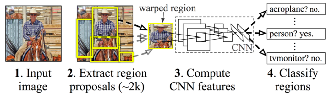
The first step is the detection of people; we perform this first task using a Region-based Convolutional Neural Network (R-CNN). CNNs are a type of network where the first neurons capture groups of pixels and these neurons form new groups for next layers by doing convolutions with Kernel filters. The neurons of the output layer return the percentage probability of an image that belong to a given class (classification). For more information, see this link. With an R-CNN we use a CNN on many regions of the image and we select those regions with a higher probability of success. There are many types of architectures based on R-CNN such as Yolo or SSD. In this exercise you will use an SSD trained model. If you want to know how SSD works, you can access this link.
Once we have detected all the people in the image, we can establish several criteria to decide which person are we going to follow.
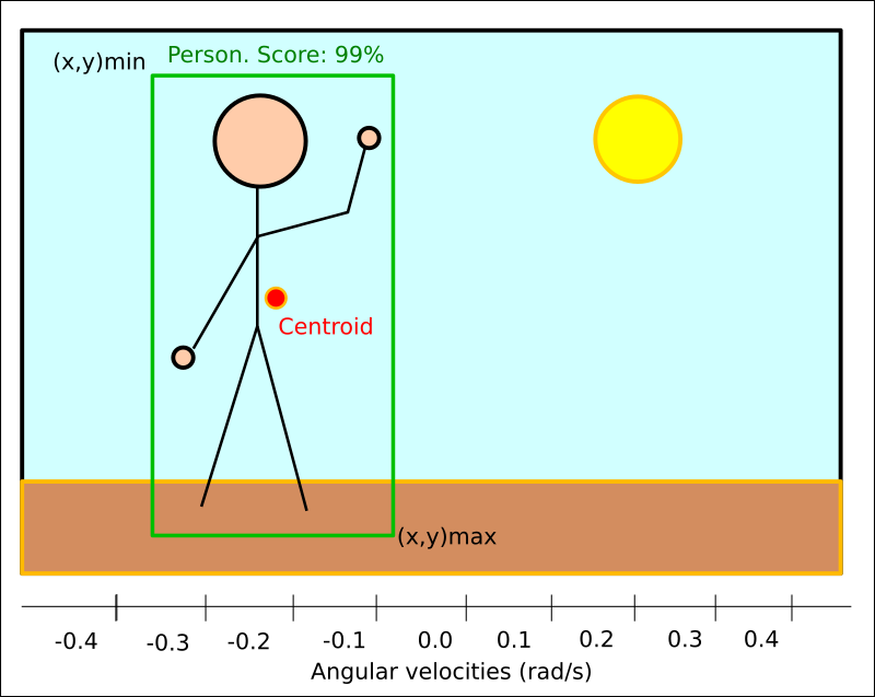
In order not to lose our target, we can use tracking algorithms. A homemade method that usually works well, consists on locating the centroid of every bounding box in each iteration and comparing it with the chosen Centroid of the previous frame. We will stay with that bounding box that have the closest centroid and the most similar area to the chosen bounding box of the previous frame.
The second step is to use the Kobuki base actuators to move and get closer to the person. To achieve this goal, we look at the location of the centroid of the candidate bounding box. Depending on the position, we will establish a certain angular speed.
An easy method to implement this is by discretized case-based behavior. We take the width of an image and divide it into X number of columns. We assign an specific angular velocity to each range, and, depending on where the centroid is, we will apply the corresponding velocity.
Another method, a bit more complicated but more efficient, is to implement a PID controller for the angular velocity. With a good design, we will obtain a more precise and less oscillatory turning response.
However, the robot moves through an environment where there may be obstacles. There is an algorithm called VFF (Virtual Force Field) that allows us to avoid collisions while following a target. It is based on the sum of attraction and repulsion vectors that determine the direction of movement.
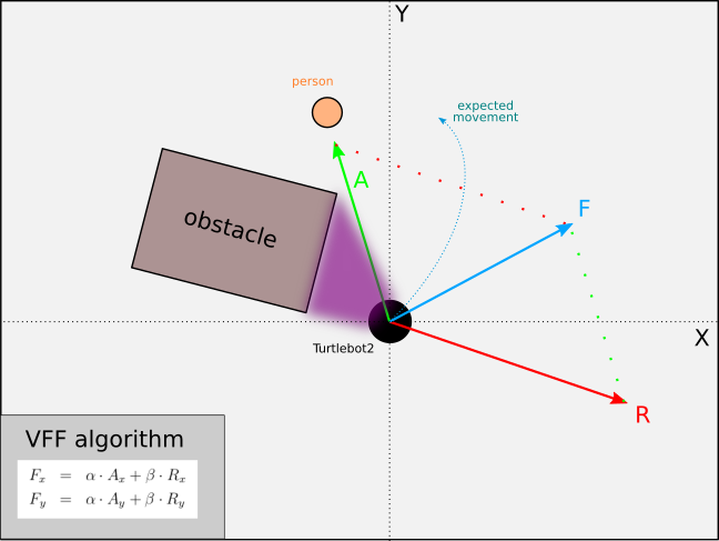
Virtual Force Field
The Virtual Force Field Algorithm works as follows:
- The robot assigns an Attraction Vector to the objective (person). With an image, you will have to use the Field of View of the camera (60 degrees) to know the angle of each pixel with the center of the image. You can set a fixed module vector with a 2D camera.
- The robot assigns a Repulsion Vector to the obstacle, according to its sensor readings that points away from the waypoint. This is done by adding all the vectors that are translated from the sensor readings.
- The robot follows the Final Vector obtained by adding the attraction and repulsion vector.
PID Controller
To understand PID Control, let us first understand what is Control in general.
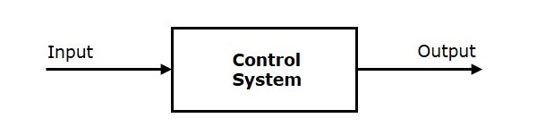
Control System
A system or set of devices, that manages, commands, directs or regulates the behavior of other devices or systems to achieve the desired results. Simply speaking, a system which controls other systems. Control Systems help a robot to execute a set of commands precisely, in the presence of unforeseen errors.
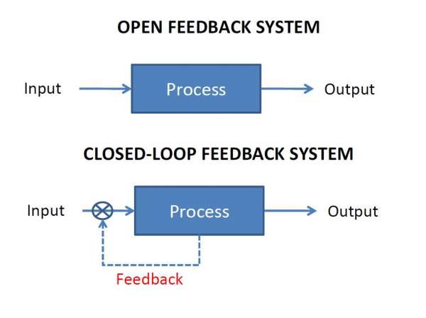
Types of Control System
Open Loop Control System
A control system in which the control action is completely independent of the output of the system. A manual control system is on Open Loop System.
Closed Loop Control System
A control system in which the output has an effect on the input quantity, in such a manner that the input will adjust itself based on the output generated. An open loop system can be converted to a closed one by providing feedback.
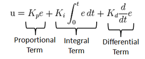
PID Control
A control loop mechanism employing feedback. A PID Controller continuously calculates an error value as the difference between desired output and the current output and applies a correction based on proportional, integral and derivative terms(denoted by P, I, D respectively).
- Proportional
Proportional Controller gives an output which is proportional to the current error. The error is multiplied with a proportionality constant to get the output. And hence, 0 if the error is 0.
- Integral
Integral Controller provides a necessary action to eliminate the offset error which is accumulated by the P Controller. It integrates the error over a period of time until its value reaches zero.
- Derivative
Derivative Controller gives an output depending on the rate of change or error with regard to time. It gives the kick start for the output, thereby increasing system response.
Videos
Reference solution of Simulated Follow Person
Contributors
- Contributors: Carlos Caminero Abad, Jose María Cañas, Lucía Lishan Chen Huang
- Maintained by Carlos Caminero Abad, Lucía Lishan Chen Huang.