Pick and Place
Goal
The goal of this exercise is to learn the underlying infrastructure of the Industrial Robot exercises (ROS 2 + MoveIt 2 + our industrial robotics HAL API) and to get familiar with the key components needed for more complex exercises.
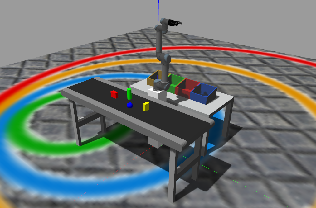
The student will program a robot arm equipped with a two-finger gripper to pick and place several objects from a conveyor and classify them by colour on the corresponding target trays. The exercise runs on Gazebo Harmonic.
Frequency API
Python
import Frequency- to import the Frequency library class. This class contains the tick function to regulate the execution rate.Frequency.tick(ideal_rate)- regulates the execution rate to the number of Hz specified. Defaults to 50 Hz.
C++
#include "Frequency.hpp"- to import the Frequency library class. This class contains the tick function to regulate the execution rate.Frequency freq = Frequency();- to instanciate the Frequency class.freq.tick(ideal_rate);- regulates the execution rate to the number of Hz specified. Defaults to 50 Hz.
Robot API
The robot is controlled through the HAL-based approach. Below you’ll find the details for the Python and C++ options.
HAL-based Implementation
Python
import HAL- to import the HAL (Hardware Abstraction Layer) library class. This class contains the functions that send and receive information to and from the Hardware (Gazebo).
Direct Kinematics
HAL.MoveAbsJ(absolute_joints, speed, wait_time)- Moves the robot to the given angular position for each joint (in degrees), at a given relative speed in the range [0-1], adding a final delay in seconds.absolute_jointsis a list of 6 joint angles.HAL.MoveSingleJ(joint_number, relative_angle, speed, wait_time)- Moves the jointjoint_number[1 to 6] by a relative angular increment (in degrees), at a given relative speed in the range [0-1], adding a final delay in seconds.
Inverse Kinematics
HAL.MoveJoint(absolute_XYZ, absolute_YPR, speed, wait_time)- Moves the robot Tool Center Point (TCP) to an absolute (X,Y,Z) pose (in metres) with an absolute orientation (Yaw,Pitch,Roll in degrees). The robot moves point-to-point, resulting in a non-linear trajectory.HAL.MoveLinear(absolute_XYZ, absolute_YPR, speed, wait_time)- Moves the robot TCP to an absolute (X,Y,Z) pose (in metres) with an absolute orientation (Yaw,Pitch,Roll in degrees) following a linear trajectory.HAL.MoveRelLinear(increment_XYZ, speed, wait_time)- Moves the robot TCP in a linear trajectory by the Cartesian displacement given inincrement_XYZ(in metres). The tool orientation is not changed.HAL.MoveRelReor(increment_YPR, speed, wait_time)- Reorients the robot TCP by the angular increments given inincrement_YPR(Yaw,Pitch,Roll in degrees). The TCP position stays fixed.
Gripper
The gripper grasps and releases objects automatically through a contact-based attachment system, so no manual attach/detach calls are required.
HAL.GripperSet(percentage_closure, wait_time)- Closes (100) or opens (0) the two-finger gripper to the given closing percentage, adding a final delay in seconds. When it starts closing (> 5) automatic attachment is enabled; when it opens (<= 5) any attached object is automatically detached.
The objects that can be automatically grasped are: blue_ball, green_cylinder, yellow_box and red_box.
C++
#include "HAL.hpp"- to import the HAL (Hardware Abstraction Layer) library class. This class contains the functions that send and receive information to and from the Hardware (Gazebo).
Direct Kinematics
HAL::MoveAbsJ(joints, speed, wait_time);- Moves the robot to the given angular position for each joint.jointsisstd::array<double, 6>in degrees,speedin [0,1],wait_timein seconds.HAL::MoveSingleJ(joint_number, relative_angle, speed, wait_time);- Moves a single joint by a relative angular increment.joint_numberin [1,6], angle in degrees.
Inverse Kinematics
HAL::MoveJoint(xyz, ypr, speed, wait_time);- Moves the TCP to an absolute Cartesian pose.xyzisstd::array<double, 3>in metres,yprin degrees.HAL::MoveLinear(xyz, ypr, speed, wait_time);- Moves the TCP in a linear trajectory to an absolute Cartesian pose.xyzin metres,yprin degrees.HAL::MoveRelLinear(xyz, speed, wait_time);- Moves the TCP by a relative Cartesian increment.xyzisstd::array<double, 3>in metres.HAL::MoveRelReor(ypr, speed, wait_time);- Reorients the TCP by relative angular increments.yprisstd::array<double, 3>in degrees.
Gripper
HAL::GripperSet(relative_closure, wait_time);- Controls the gripper.relative_closurein [0,100] (0 = fully open, 100 = fully closed). When closing (> 5) contact-based automatic attachment is enabled; when opening (<= 5) the attached object is automatically released.
In order to use the HAL-based controls you must include the following lines:
#include "HAL.hpp"
#include "Frequency.hpp"

void exercise() {
    Frequency freq = Frequency();
    // Enter sequential code!

    while (true)
    {
        // Enter iterative code!
        freq.tick();


    }
}
Argument examples
Data targets for MoveAbsJ (joint angles, in degrees)
absj_home = [0, -90, 70, -70, -90, 0]
Absolute XYZ poses for MoveJoint and MoveLinear (in metres, world frame)
aprox_yellow_box    = [0.6, 0.3, 0.4]
aprox_yellow_target = [-0.4, -0.45, 0.4]
Absolute YPR orientations for MoveJoint and MoveLinear (in degrees)
YPR_pick  = [180, 0, -90]
YPR_place = [0, 90, 0]
Cartesian increments for MoveRelLinear, [Ax, Ay, Az] in metres
decrease_z_10 = [0, 0, -0.10]
increase_z_20 = [0, 0,  0.20]
Theory
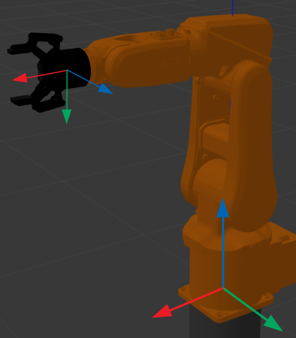
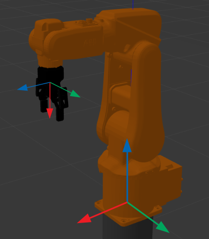
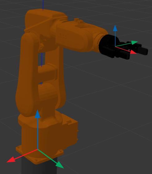
TCP orientation (Yaw, Pitch, Roll)
The MoveJoint and MoveLinear functions receive the TCP orientation as a [Yaw, Pitch, Roll] list, in degrees, expressed in the world frame. At [0, 0, 0] the tool frame is aligned with the world frame:
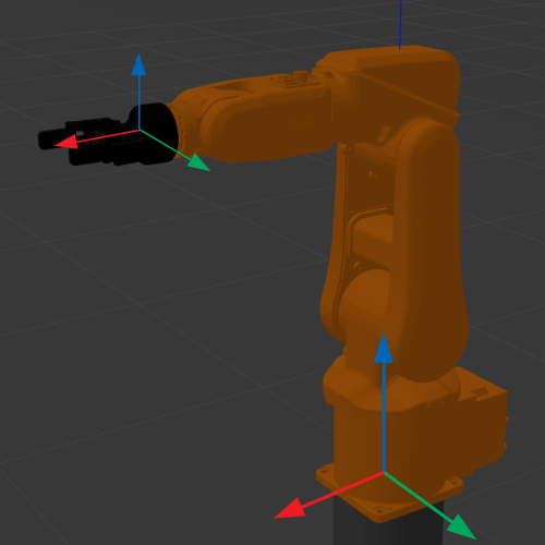
A single 90º rotation on each axis (yaw, pitch or roll) reorients the tool as follows:
Relationship among ROS 2, MoveIt 2, Gazebo and the JdeRobot API
- ROS (Robot Operating System) is a robotics middleware which contains a set of open source libraries for developing robot applications.
- MoveIt is an open source Motion Planning framework for industrial robots which integrates motion planning, collision checking, manipulation and 3D perception capabilities.
- RViz is a 3D visualization tool for ROS. Many ROS topics can be visualized in RViz, including the planning scene of the MoveIt move group, but it does not contain any physics simulation capability.
- Gazebo is a physics simulator mainly used for robot simulation.
- The HAL API provided by JdeRobot Robotics Academy is built on top of the above tools and the IFRA Cranfield repositories (see References), so you do not need to learn all of them to start simulating industrial robot manipulation.
Hints
Simple hints to help you solve the Pick and Place exercise.
Where to insert and run the code
In the launched web page, type your code in the text editor and run it by pressing the play button:
import HAL
# Enter sequential code here!

while True:
    # Enter iterative code here!
Why does the robot sometimes fail to move to a desired pose?
The most likely reason is that your specified pose is unreachable for the robot arm, so MoveIt cannot plan a trajectory from the current pose to the desired pose within the allowed time. You will see a warning like this when that happens:
Fail: ABORTED: No motion plan found. No execution attempted.
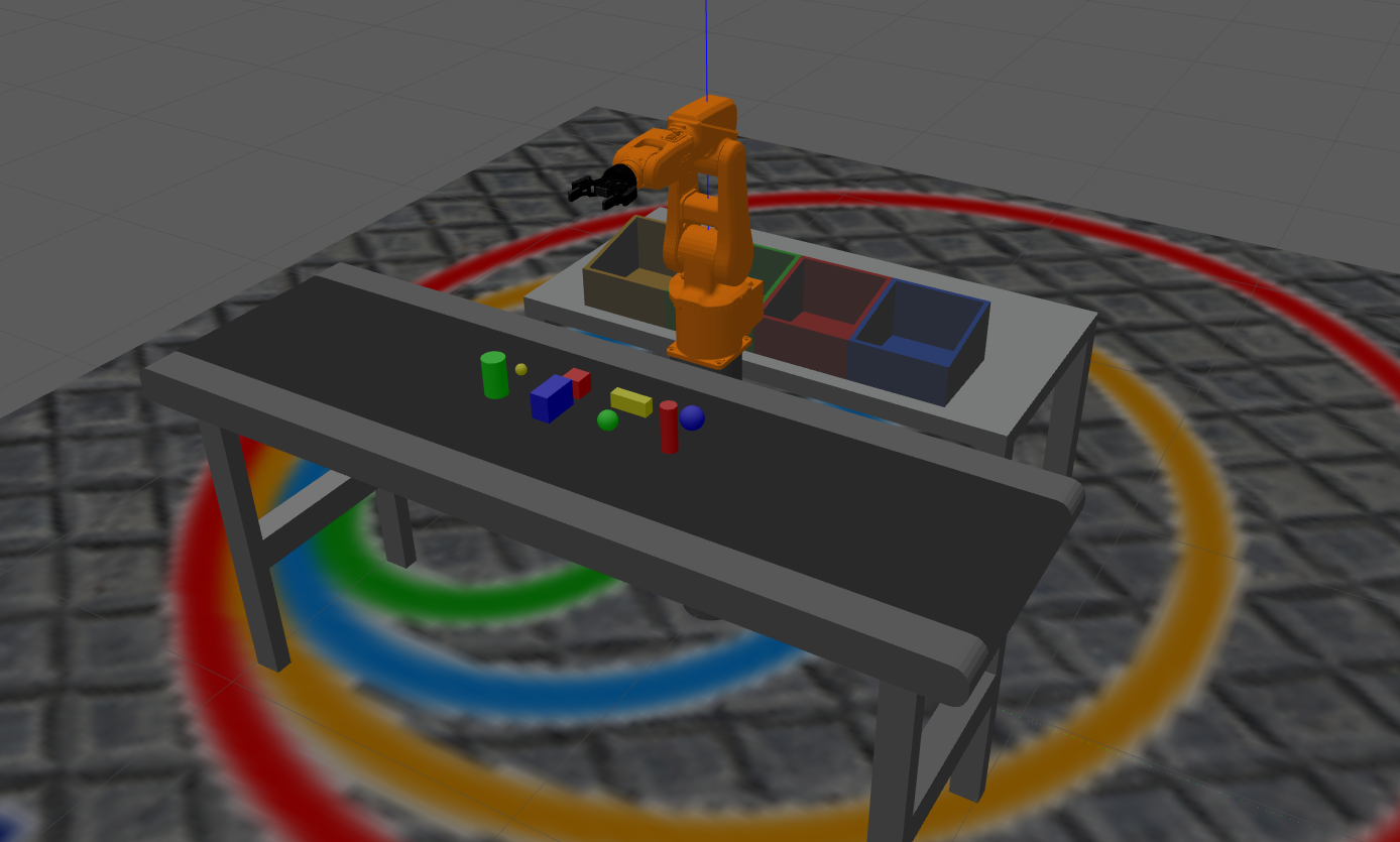
Object and target lists
Object list. The four objects are located on a conveyor that is 1 m tall.
- yellow_box — Size (l,w,h) = (7,5,10) cm — Pose (x,y) = (0.6, 0.3) m
- red_box — Size (l,w,h) = (5,10,8) cm — Pose (x,y) = (0.6, -0.3) m
- blue_ball — Size (r) = (4) cm — Pose (x,y) = (0.7, 0.1) m
- green_cylinder — Size (r,h) = (4,15) cm — Pose (x,y) = (0.5, -0.1) m
Target list. The four targets are located on a table that is 0.8 m tall.
- red_target — Pose (x,y) = (-0.4, 0.15) m
- green_target — Pose (x,y) = (-0.4, -0.15) m
- blue_target — Pose (x,y) = (-0.4, 0.45) m
- yellow_target — Pose (x,y) = (-0.4, -0.45) m
Videos
Contributors
- Contributors: Diego Martín, José María Cañas and Javier Izquierdo.
References
- IFRA-Cranfield (2023). ROS 2 Sim-to-Real Robot Control. https://github.com/IFRA-Cranfield/ros2_SimRealRobotControl
- https://moveit.ros.org/
- https://gazebosim.org/