Position Control
Goal
The goal of this exercise is to implement a local navigation algorithm through the use of a PID controller.
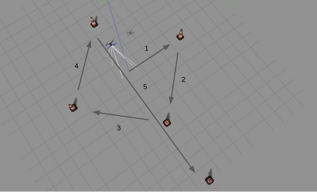
For this exercise, a world has been designed in gazebo that contains the Iris quadrotor and 5 beacons arranged in a cross. The task is to program the drone to follow the route as given in the picture below.
Installing and Launching
-
Download Docker. Windows users should choose WSL 2 backend Docker installation if possible, as it has better performance than Hyper-V.
-
Pull the current distribution of RoboticsBackend:
docker pull jderobot/robotics-backend:latest
- In order to obtain optimal performance, Docker should be using multiple CPU cores. In case of Docker for Mac or Docker for Windows, the VM should be assigned a greater number of cores.

- It is recommended to use the latest image. However, older distributions of RoboticsBackend can be found [here](https://hub.docker.com/r/jderobot/robotics-backend/tags).

### How to perform the exercises?
- Start a new docker container of the image and keep it running in the background:

	```bash
docker run --rm -it -p 7164:7164 -p 2303:2303 -p 1905:1905 -p 8765:8765 -p 6080:6080 -p 1108:1108 -p 7163:7163 jderobot/robotics-backend
-
On the local machine navigate to 127.0.0.1:7164/ in the browser and choose the desired exercise.
-
Wait for the Connect button to turn green and display “Connected”. Click on the “Launch” button and wait for some time until an alert appears with the message
Connection Establishedand button displays “Ready”. -
The exercise can be used after the alert.
Enable GPU Acceleration
- Follow the advanced launching instructions from here.
Optional: Store terminal output
- To store the terminal output of manager.py and launch.py to a file execute the following docker run command and keep it running in the background:
docker run -it --rm -v $HOME/.roboticsacademy/log/:/root/.roboticsacademy/log/ --device /dev/dri -p 7164:7164 -p 2303:2303 -p 1905:1905 -p 8765:8765 -p 6080:6080 -p 1108:1108 -p 2304:2304 -p 1904:1904 jderobot/robotics-backend --logs
- The log files will be stored inside
$HOME/.roboticsacademy/{year-month-date-hours-mins}/. After the session, usemoreto view the logs, for example:
more $HOME/.roboticsacademy/log/2021-11-06-14-45/manager.log
Where to insert the code?
In the launched webpage, type your code in the text editor,
import WebGUI
import HAL
# Enter sequential code!

while True:
    # Enter iterative code!
Using the Interface
-
Control Buttons: The control buttons enable the control of the interface. Play button sends the code written by User to the Robot. Stop button stops the code that is currently running on the Robot. Save button saves the code on the local machine. Load button loads the code from the local machine. Reset button resets the simulation(primarily, the position of the robot).
-
Brain and GUI Frequency: This input shows the running frequency of the iterative part of the code (under the
while True:). A smaller value implies the code runs less number of times. A higher value implies the code runs a large number of times. The numerator is the one set as the Measured Frequency who is the one measured by the computer (a frequency of execution the computer is able to maintain despite the commanded one) and the input (denominator) is the Target Frequency which is the desired frequency by the student. The student should adjust the Target Frequency according to the Measured Frequency. -
RTF (Real Time Factor): The RTF defines how much real time passes with each step of simulation time. A RTF of 1 implies that simulation time is passing at the same speed as real time. The lower the value the slower the simulation will run, which will vary depending on the computer.
-
Pseudo Console: This shows the error messages related to the student’s code that is sent. In order to print certain debugging information on this console. The student can use the
print()command in the Editor.
Frequency API
Python
import Frequency- to import the Frequency library class. This class contains the tick function to regulate the execution rate.Frequency.tick(ideal_rate)- regulates the execution rate to the number of Hz specified. Defaults to 50 Hz.
C++
#include "Frequency.hpp"- to import the Frequency library class. This class contains the tick function to regulate the execution rate.Frequency freq = Frequency();- to instanciate the Frequency class.freq.tick(ideal_rate);- regulates the execution rate to the number of Hz specified. Defaults to 50 Hz.
Robot API
This exercise now supports ROS 2-direct implementation in addition to the original HAL-based approach. Below you’ll find the details for both options.
HAL-based Implementation
Python
import HAL- to import the HAL (Hardware Abstraction Layer) library class. This class contains the functions that send and receive information to and from the Hardware (Gazebo).-
import WebGUI- to import the WebGUI (Web Graphical User Interface) library class. This class contains the functions used to view the debugging information, like image widgets. HAL.get_position()- Returns the actual position of the drone as a numpy array [x, y, z], in m.HAL.get_velocity()- Returns the actual velocities of the drone as a numpy array [vx, vy, vz], in m/s.HAL.get_yaw_rate()- Returns the actual yaw rate of the drone, in rad/s.HAL.get_orientation()- Returns the actual roll, pitch and yaw of the drone as a numpy array [roll, pitch, yaw], in rad.HAL.get_roll()- Returns the roll angle of the drone, in radHAL.get_pitch()- Returns the pitch angle of the drone, in rad.HAL.get_yaw()- Returns the yaw angle of the drone, in rad.HAL.get_landed_state()- Returns 1 if the drone is on the ground (landed), 2 if the drone is in the air and 4 if the drone is landing. 0 could be also returned if the drone landed state is unknown.HAL.set_cmd_pos(x, y, z, az)- Commands the position (x,y,z) of the drone, in m and the yaw angle (az) (in rad) taking as reference the first takeoff point (map frame).HAL.set_cmd_vel(vx, vy, vz, az)- Commands the linear velocity of the drone in the x, y and z directions (in m/s) and the yaw rate (az) (rad/s) in its body fixed frame.HAL.set_cmd_mix(vx, vy, z, az)- Commands the linear velocity of the drone in the x, y directions (in m/s), the height (z) related to the takeoff point and the yaw rate (az) (in rad/s).HAL.takeoff(height)- Takeoff at the current location, to the given height (in m).HAL.land()- Land at the current location.HAL.get_frontal_image()- Returns the latest image from the frontal camera as a OpenCV cv2_image.HAL.get_ventral_image()- Returns the latest image from the ventral camera as a OpenCV cv2_image.WebGUI.showImage(cv2_image)- Shows an image of the camera in the right panel of the WebGUI.WebGUI.showLeftImage(cv2_image)- Shows another image of the camera in the left panel of the WebGUI.
C++
#include "HAL.hpp"- to import the HAL (Hardware Abstraction Layer) library class. This class contains the functions that send and receive information to and from the Hardware (Gazebo).#include "WebGUI.hpp"- to import the WebGUI (Web Graphical User Interface) library class. This class contains the functions used to view the debugging information, like image widgets.HAL::get_pose3d();- Returns the current pose of the drone as aHAL::Pose3dstruct with fieldsx,y,z(position in m),yaw,pitch,roll(orientation in rad) andtimeStamp.HAL::get_velocity();- Returns the current velocity of the drone as aHAL::Velocity3dstruct with fieldsvx,vy,vz(in m/s) andyaw_rate(in rad/s).HAL::get_landed_state();- Returns 1 if the drone is on the ground (landed), 2 if the drone is in the air and 4 if the drone is landing. 0 could be also returned if the drone landed state is unknown.HAL::set_cmd_pos(x, y, z, az);- Commands the position (x,y,z) of the drone, in m and the yaw angle (az) (in rad) taking as reference the first takeoff point (map frame).HAL::set_cmd_vel(vx, vy, vz, az);- Commands the linear velocity of the drone in the x, y and z directions (in m/s) and the yaw rate (az) (rad/s) in its body fixed frame.HAL::set_cmd_mix(vx, vy, z, az);- Commands the linear velocity of the drone in the x, y directions (in m/s), the height (z) related to the takeoff point and the yaw rate (az) (in rad/s).HAL::takeoff(height);- Takeoff at the current location, to the given height (in m).HAL::land();- Land at the current location.HAL::get_frontal_image();- Returns the latest image from the frontal camera as a cv::Mat.HAL::get_ventral_image();- Returns the latest image from the ventral camera as a cv::Mat.WebGUI::show_right_image(image);- Shows an image in the right panel of the WebGUI (cv::Mat).WebGUI::show_left_image(image);- Shows an image in the left panel of the WebGUI (cv::Mat).
In order to use the HAL-based controls you must include the following lines:
#include "HAL.hpp"
#include "WebGUI.hpp"
#include "Frequency.hpp"

void exercise() {
    Frequency freq = Frequency();
    // Enter sequential code!

    while (true)
    {
        // Enter iterative code!
        freq.tick();


    }
}
Beacons
The five beacons are not a queryable API: they are fixed ground-truth positions, given here in world frame (metres), matching the numbered markers placed in the world:
- beacon1 (0.0, 18.0, 0.5)
- beacon2 (18.0, 0.0, 2.0)
- beacon3 (0.0, -18.0, 3.5)
- beacon4 (-18.0, 0.0, 5.0)
- beacon5 (23.0, 23.0, 6.5)
Your code decides how to visit them: reaching each one, in order, is up to your own position control logic on top of HAL.set_cmd_pos/HAL::set_cmd_pos.
ROS 2-direct Implementation
Use standard ROS 2 topics for direct communication with the simulation.
This exercise uses Aerostack2, so the ROS 2-direct version is more advanced than in ground robots. For more information about Aerostack 2
The drone namespace is /drone.
-
/drone/frontal_cam/image_raw- Subscribe to this topic to receive the frontal camera image. Message type:sensor_msgs/msg/Image -
/drone/ventral_cam/image_raw- Subscribe to this topic to receive the ventral camera image. Message type:sensor_msgs/msg/Image -
/drone/self_localization/twist- Subscribe to this topic to receive the drone twist, including yaw rate. Message type:geometry_msgs/msg/TwistStamped -
/drone/motion_reference/pose- Publish to this topic to send position references with orientation. Message type:geometry_msgs/msg/PoseStamped -
/drone/motion_reference/twist- Publish to this topic to send velocity references. Message type:geometry_msgs/msg/TwistStamped -
/drone/platform/info- Subscribe to this topic to receive the platform state information. Message type:as2_msgs/msg/PlatformInfo -
/drone/platform/state_machine_event- Service used for takeoff and landing state transitions. Service type:as2_msgs/srv/SetPlatformStateMachineEvent
For image debugging:
-
/webgui/image_debug_right- Publish to this topic to display a debug image in the right panel of the WebGUI. Message type:sensor_msgs/msg/Image -
/webgui/image_debug_left- Publish to this topic to display a debug image in the left panel of the WebGUI. Message type:sensor_msgs/msg/Image
Python
Note: Ensure this import is included in your script to access the Web GUI functionalities.
import WebGUI - to enable the Web GUI for visualizing camera images.
To have frequency control you need to use standard ROS 2 mechanisms to manage loop timing:
rclpy.spin()- Event-driven execution using callbacks.rclpy.spin_once()- Single-step processing, often with custom timers.rclpy.Rate()- Loop-based frequency control.
Note
WebGUI already initializes rclpy internally, so this should be taken into account when building a direct ROS 2 solution.
C++
In order to use direct ros controls you must include the following lines:
#ifndef USER_NODE
#define USER_NODE

#include "rclcpp/rclcpp.hpp"

class UserNode : public rclcpp::Node {
  // Your class
};

#endif
You must define USER_NODE and a UserNode node class.
To have frequency control you may use a timer and a control function as follows:
  UserNode() : Node("user_node")
  {
    // More subscribers and publishers
    timer_ = create_wall_timer(100ms, std::bind(&UserNode::control_cycle, this));
  };

// More Code

  void control_cycle(){
    // Your function
  };
Theory
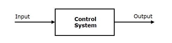
PID Control is the main fundamental behind this exercise. To understand PID Control, let us first understand what is Control in general.
Control System
A system of devices or set of devices, that manages, commands, directs or regulates the behavior of other devices or systems to achieve the desired results. Simply speaking, a system which controls other systems. Control Systems help a robot to execute a set of commands precisely, in the presence of unforeseen errors.
Types of Control System
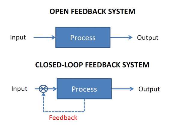
Open Loop Control System
A control system in which the control action is completely independent of the output of the system. A manual control system is on Open Loop System.
Closed Loop Control System
A control system in which the output has an effect on the input quantity in such a manner that the input will adjust itself based on the output generated. An open loop system can be converted to a closed one by providing feedback.
PID Control
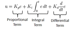
A control loop mechanism employing feedback. A PID Controller continuously calculates an error value as the difference between desired output and the current output and applies a correction based on proportional, integral and derivative terms(denoted by P, I, D respectively).
- Proportional
Proportional Controller gives an output which is proportional to the current error. The error is multiplied with a proportionality constant to get the output. And hence, is 0 if the error is 0.
- Integral
Integral Controller provides a necessary action to eliminate the offset error which is accumulated by the P Controller.It integrates the error over a period of time until the error value reaches to zero.
- Derivative
Derivative Controller gives an output depending upon the rate of change or error with respect to time. It gives the kick start for the output thereby increasing system response.
Tuning Methods
In order for the PID equation to work, we need to determine the constants of the equation. There are 3 constants called the gains of the equation. We have 2 main tuning methods for this.
- Trial and Error
It is a simple method of PID controller tuning. While system or controller is working, we can tune the controller. In this method, first we have to set Ki and Kd values to zero and increase proportional term (Kp) until system reaches to oscillating behavior. Once it is oscillating, adjust Ki (Integral term) so that oscillations stops and finally adjust D to get fast response.
- Zeigler Nichols method
Zeigler-Nichols proposed closed loop methods for tuning the PID controller. Those are continuous cycling method and damped oscillation method. Procedures for both methods are same but oscillation behavior is different. In this, first we have to set the p-controller constant, Kp to a particular value while Ki and Kd values are zero. Proportional gain is increased till system oscillates at constant amplitude.
Hints
Simple hints provided to help you solve the position_control exercise. Please note that the full solution has not been provided.
How do I know the position of each beacon?
They are fixed, listed in the Beacons section above. There is no function to query them at runtime, your solution should hardcode them the same way the exercise’s own reference solution does.
Directional control. How should drone yaw be handled?
If you don’t take care of the drone yaw angle or yaw_rate in your code (keeping them always equal to zero), you will fly in what’s generally called Heads Free Mode. The drone will always face towards its initial orientation, and it will fly sideways or even backwards when commanded towards a target destination. Multi-rotors can easily do that, but what’s not the best way of flying a drone.
In this exercise, your drone should follow the path similarly to how a fixed-wing aircraft would do, namely nose forward. Then, you’ll have to implement by yourself some kind of directional control, to rotate the nose of your drone left or right using yaw angle, or yaw_rate.
However, you can first solve the exercise ignoring the yaw angle (heads free) and the improve it using a nose forward mode.
This might help, if you know your current position and your target one, you can easily compute the direction (yaw angle) the drone must be turned to by applying some elementary geometry. Probably both math.sqrt() and math.atan2() Python functions will be very useful for you here.
Coding the Controller
The Controller can be designed in various configurations. 3 configurations have been described in detail below:
-
P Controller The simplest way to do the assignment is using the P Controller. Just find the error which is the difference between our Set Point (the point where our drone should be heading) and the Current Output (where the drone is actually heading). Keep adjusting the value of the constant, till we get a value where there occurs no unstable oscillations and no slow response.
-
PD Controller This is an interesting way to see the effect of Derivative on the Control. For this, we need to calculate the derivative of the output we are receiving. Since, we are dealing with discrete outputs in our case, we simply calculate the difference between our previous error and the present error, then adjust the proportional constant. Adjust this value along with the P gain to get a good result.
-
PID Controller This is the complete implemented controller. Now, to add the I Controller we need to integrate the output from the point where error was zero, to the present output. While dealing with discrete outputs, we can achieve this using accumulated error. Then, comes the task of adjustment of gain constants till we get our desired result.
Do I need to know when the drone is in the air?
No, you can solve this exercise without taking care of the land state of the drone. However, it could be a great enhancement to your blocking position control function if you make it only work when the drone is actually flying, not on the ground.
Videos
Demonstrative video of the solution
Contributors
- Contributors: Nikhil Khedekar, Jose Maria Cañas, Diego Martín, Pedro Arias and Arkajyoti Basak.
- Maintained by Pedro Arias and Arkajyoti Basak.