Visual Odometry with RGBD
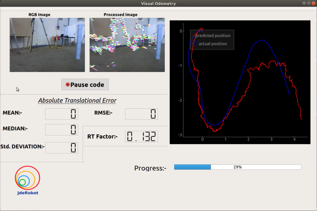
The objective of this exercise is to implement the logic of a RGBD visual odometry algorithm. The performance/accuracy of the users’ algorithm will be shown on the GUI of the exercise.
Instructions
Installation
-
Requirements - (install these packages before proceeding).
pyqtgraph —
sudo pip install pyqtgraphconfigparser —
sudo pip install configparser
How to run
To launch the exercise, follow the steps below:
-
Download the rosbag file from here. https://gsyc.urjc.es/jmplaza/slam/rgbd_dataset_freiburg2_pioneer_slam_truncated.bag
-
Place the rosbag file in the same directory as of this exercise and replace the name of the rosbag file in the ‘visual_odometry.cfg’ or mention the full path of the rosbag file.
-
Execute the exercise with GUI :
python visual_odom.py
How to do the practice:
To carry out the practice, you must edit the MyAlgorithm.py file and insert the algorithm logic into it.
Where to insert the code
    def execute(self):
        # demo code (replace with your code )
        print ("Runing")

        #Getting sensor data
        data = self.getReadings( 'color_img' , 'depth_img' )

        #color image
        color_image = data.color_img

        #depth image
        depth_image = data.depth_img

        #set processed image
        self.set_processed_image(color_img)

        #set predicted pose
        x = 1
        y = 1
        self.set_predicted_pose(x,y,timestamp) #timestamp of the predicted position.
API’s:
Sensors available: - ‘color_img’ , ‘depth_img’, ‘orientation’ , ‘accelerometer’ , ‘scan’ (laser scan) .
-
data = self.getReadings('color_img' , 'depth_img')- to get the next available RGB image and the Depth image from the ROSbag file. ( only one pair of RGB image and Depth image will be provided per call). color_img = data.color_img- to get the RGB image from the object ‘data’.depth_img = data.depth_img- to get the Depth image from the object ‘data’.color_img_t = data.color_img_t- to get the timestamp of the RGB image.depth_img_t = data.depth_img_t- to get the timestamp of the Depth image.
Similarly , to get the readings of other sensors the required sensors name has to be mentioned while calling data = self.getReadings() separated by commas (,).
data.color_img - for RGB color image and data.color_img_t for its timestamp.
data.depth_img - for depth image and data.depth_img_t for its timestamp.
data.accelerometer - for accelerometer data and data.accelerometer_t for its timestamp.
data.orientation - for orientation data and data.orientation_t for its timestamp.
data.scan - for laser scan data and data.scan_t for its timestamp.
(You can mention as many as sensors names during calling the data = self.getReadings() method).
self.set_processed_image(color_img)- to set the processed RGB image to be shown on the GUI.self.set_predicted_pose(x,y,timestamp)- to set the position and timestamp of the predict pose by the algorithm ( x and y should be floating point number.)self.set_predicted_path(path)- to set predicted path at once /or reset the previously set predicted poses at once —- path should be Nx2 (numpy array or python list) [x,y]. (optional)
How does data from multiple sensors are read and provided to the users by the self.getReadings() method?
Let’s assume that the user only wants the data from ‘color_img’ , ‘depth_img’ and ‘scan’ sensors. So the user will call the method like this data = self.getReadings('color_img' , 'depth_img','scan') . Internally the program then starts to read the messages ROSbag file chronologically and if any of the above mentioned sensor topic is found , the topic data gets stored in its respective attribute.The program continues to read the topics in ROSbag file sequentially until all the sensor data required by the user are read and stored in its respective attributes. And since the data frequency of different sensors are different so while reading the sensor data sequentially the latest data from a particular sensor will override it’s previous value.
REMEMBER : By this method only the sensor name mentioned while calling this method will have the sensor data . e.g. - In the above example (data = self.getReadings('color_img' , 'depth_img','scan') ) only data.color_img , data.depth_img and data.scan will contain its’ respective sensor data and other attributes like data.accelerometer and data.orientation will contain NoneType data.
Data Types:
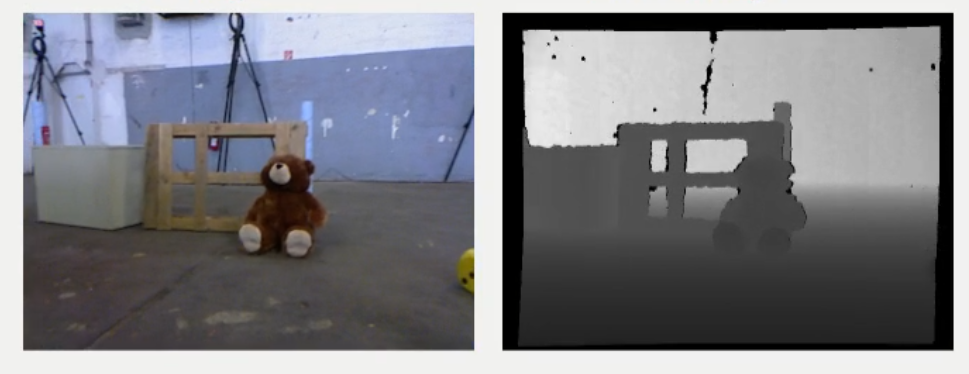
- The Color RGB image is provided in 640×480 8-bit RGB format.
- The Depth image is provided in 32-bit floating point precision.
- The Timestamps are floating point numbers.
- The laser scan data is provided in numpy array format.
-
Orientation data can be accessed as follows:
qz = data.orientation[‘qz’]
qw = data.orientation[‘qw’]
‘qx’ and ‘qy’ are essentially zero(since we are computing 2D odometry).
-
Accelerometer data can be accessed as follows:
ax = data.accelerometer[‘x’]
ay = data.accelerometer[‘y’]
‘az’ is essentially zero(since we are computing 2D odometry).
- For more details about the dataset refer to the original page of the TUM RGBD dataset https://vision.in.tum.de/data/datasets/rgbd-dataset/file_formats#ros_bag.
Theory
- Visual Odometry is the process of incrementally estimating the pose of the vehicle by examining the changes that motion induces on the images of its onboard cameras.
- Contrary to wheel odometry, VO is not affected by wheel slip in uneven terrain or other adverse conditions.
- More accurate trajectory estimates compared to wheel odometry .
- VO computes the camera path incrementally (pose after pose).
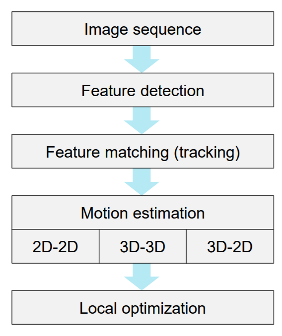
Here is a flowchart explaining the step-by-step process for implementing an visual odometry algorithm.
More detailed deliberation on visual odometry is provided here.
-
https://sites.google.com/site/scarabotix/tutorial-on-visual-odometry/
-
http://www.cs.toronto.edu/~urtasun/courses/CSC2541/03_odometry.pdf
Hint
Simple hints provided to help you solve the exercise. Please note that the following hint is only a suggestive approach. Any other algorithm to solve the exercise is acceptable.
1) Detect features from the first available RGB image using FAST algorithm.
2) Track the detected features in the next available RGB image using Lucas-Kanade Optical Flow Algorithm.
3) Create the 3D pointcloud (of the tracked/detected feature points) of the latest two available RGB image with the help of their depth image .
4) Estimate the motion between two consecutive 3D pointclouds.
5) Concatenate the Rotation and Translational information to obtain the predicted path.
Following research paper can be used as a reference: Visual Odometry and Mapping for Autonomous Flight Using an RGB-D Camera
Demonstration video:
Contributors
-
Contributors: Debrup Datta, Jose María Cañas
-
Maintained by Debrup Datta.