Power Tower Inspection
Goal
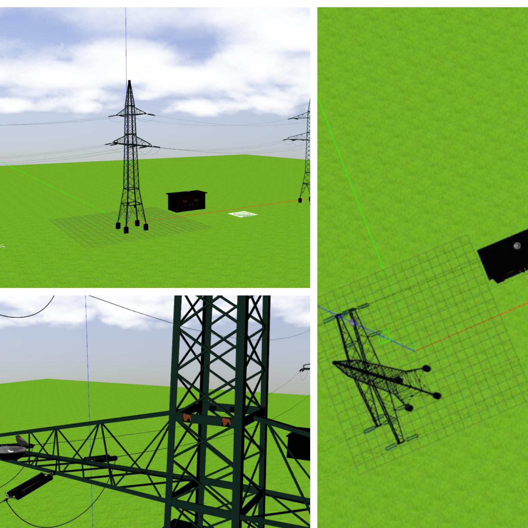
The goal of this exercise is to implement the logic that allows a quadrotor to perform navigation and an inspection of the power towers, the electrical wires connecting them and the insulators (spring like object) attached to them. The task for the drone to execute is to visualise these defects and locate them and then land or keep hovering (according to the student’s choice) after the objective completion
Where to insert the code?
In the launched webpage, type your code in the text editor,
import WebGUI
import HAL
# Enter sequential code!

while True:
    # Enter iterative code!
Using the Interface
-
Control Buttons: The control buttons enable the control of the interface. Play button sends the code written by User to the Robot. Stop button stops the code that is currently running on the Robot. Save button saves the code on the local machine. Load button loads the code from the local machine. Reset button resets the simulation(primarily, the position of the robot).
-
Brain and GUI Frequency: This input shows the running frequency of the iterative part of the code (under the
while True:). A smaller value implies the code runs less number of times. A higher value implies the code runs a large number of times. The numerator is the one set as the Measured Frequency who is the one measured by the computer (a frequency of execution the computer is able to maintain despite the commanded one) and the input (denominator) is the Target Frequency which is the desired frequency by the student. The student should adjust the Target Frequency according to the Measured Frequency. -
RTF (Real Time Factor): The RTF defines how much real time passes with each step of simulation time. A RTF of 1 implies that simulation time is passing at the same speed as real time. The lower the value the slower the simulation will run, which will vary depending on the computer.
-
Pseudo Console: This shows the error messages related to the student’s code that is sent. In order to print certain debugging information on this console. The student can use the
print()command in the Editor.
Frequency API
Python
import Frequency- to import the Frequency library class. This class contains the tick function to regulate the execution rate.Frequency.tick(ideal_rate)- regulates the execution rate to the number of Hz specified. Defaults to 50 Hz.
C++
#include "Frequency.hpp"- to import the Frequency library class. This class contains the tick function to regulate the execution rate.Frequency freq = Frequency();- to instanciate the Frequency class.freq.tick(ideal_rate);- regulates the execution rate to the number of Hz specified. Defaults to 50 Hz.
Robot API
This exercise now supports ROS 2-direct implementation in addition to the original HAL-based approach. Below you’ll find the details for both options.
HAL-based Implementation
Python
import HAL- to import the HAL(Hardware Abstraction Layer) library class. This class contains the functions that sends and receives information to and from the Hardware(Gazebo).-
import WebGUI- to import the GUI(Graphical User Interface) library class. This class contains the functions used to view the debugging information, like image widgets. HAL.get_position()- Returns the actual position of the drone as a numpy array [x, y, z], in m.HAL.get_velocity()- Returns the actual velocities of the drone as a numpy array [vx, vy, vz], in m/sHAL.get_yaw_rate()- Returns the actual yaw rate of the drone, in rad/s.HAL.get_orientation()- Returns the actual roll, pitch and yaw of the drone as a numpy array [roll, pitch, yaw], in rad.HAL.get_roll()- Returns the roll angle of the drone, in radHAL.get_pitch()- Returns the pitch angle of the drone, in rad.HAL.get_yaw()- Returns the yaw angle of the drone, in rad.HAL.get_landed_state()- Returns 1 if the drone is on the ground (landed), 2 if the drone is in the air and 4 if the drone is landing. 0 could be also returned if the drone landed state is unknown.
C++
#include "HAL.hpp"- to import the HAL (Hardware Abstraction Layer) library class. This class contains the functions that send and receive information to and from the Hardware (Gazebo).#include "WebGUI.hpp"- to import the WebGUI (Web Graphical User Interface) library class. This class contains the functions used to view the debugging information, like image widgets.HAL::get_pose3d();- Returns the current pose of the drone as aHAL::Pose3dstruct with fieldsx,y,z(position in m),yaw,pitch,roll(orientation in rad) andtimeStamp.HAL::get_velocity();- Returns the current velocity of the drone as aHAL::Velocity3dstruct with fieldsvx,vy,vz(in m/s) andyaw_rate(in rad/s).HAL::get_landed_state();- Returns 1 if the drone is on the ground (landed), 2 if the drone is in the air and 4 if the drone is landing. 0 could be also returned if the drone landed state is unknown.HAL::set_cmd_pos(x, y, z, az);- Commands the position (x,y,z) of the drone, in m and the yaw angle (az) (in rad) taking as reference the first takeoff point (map frame).HAL::set_cmd_vel(vx, vy, vz, az);- Commands the linear velocity of the drone in the x, y and z directions (in m/s) and the yaw rate (az) (rad/s) in its body fixed frame.HAL::set_cmd_mix(vx, vy, z, az);- Commands the linear velocity of the drone in the x, y directions (in m/s), the height (z) related to the takeoff point and the yaw rate (az) (in rad/s).HAL::takeoff(height);- Takeoff at the current location, to the given height (in m).HAL::land();- Land at the current location.HAL::get_frontal_image();- Returns the latest image from the frontal camera as a cv::Mat.HAL::get_ventral_image();- Returns the latest image from the ventral camera as a cv::Mat.WebGUI::show_right_image(image);- Shows an image in the right panel of the WebGUI (cv::Mat).WebGUI::show_left_image(image);- Shows an image in the left panel of the WebGUI (cv::Mat).
In order to use the HAL-based controls you must include the following lines:
#include "HAL.hpp"
#include "WebGUI.hpp"
#include "Frequency.hpp"

void exercise() {
    Frequency freq = Frequency();
    // Enter sequential code!

    while (true)
    {
        // Enter iterative code!
        freq.tick();


    }
}
Actuators and drone control
The three following drone control functions are non-blocking, i.e. each time you send a new command to the aircraft it immediately discards the previous control command.
1. Position control
HAL.set_cmd_pos(x, y, z, az)- Commands the position (x,y,z) of the drone, in m and the yaw angle (az) (in rad) taking as reference the first takeoff point (map frame)
2. Velocity control
HAL.set_cmd_vel(vx, vy, vz, az)- Commands the linear velocity of the drone in the x, y and z directions (in m/s) and the yaw rate (az) (rad/s) in its body fixed frame
3. Mixed control
HAL.set_cmd_mix(vx, vy, z, az)- Commands the linear velocity of the drone in the x, y directions (in m/s), the height (z) related to the takeoff point and the yaw rate (az) (in rad/s)
Drone takeoff and land
Besides using the buttons at the drone teleoperator GUI, taking off and landing can also be controlled from the following commands in your code:
HAL.takeoff(height)- Takeoff at the current location, to the given height (in m)HAL.land()- Land at the current location.
Drone cameras
HAL.get_frontal_image()- Returns the latest image from the frontal camera as a OpenCV cv2_imageHAL.get_ventral_image()- Returns the latest image from the ventral camera as a OpenCV cv2_image
GUI
GUI.showImage(cv2_image)- Shows a image of the camera in the GUIGUI.showLeftImage(cv2_image)- Shows another image of the camera in the GUI
ROS 2-direct Implementation
Use standard ROS 2 topics for direct communication with the simulation.
This exercise uses Aerostack2, so the ROS 2-direct version is more advanced than in ground robots. For more information about Aerostack 2
The drone namespace is /drone0.
-
/drone0/frontal_cam/image_raw- Subscribe to this topic to receive the frontal camera image. Message type:sensor_msgs/msg/Image -
/drone0/ventral_cam/image_raw- Subscribe to this topic to receive the ventral camera image. Message type:sensor_msgs/msg/Image -
/drone0/self_localization/twist- Subscribe to this topic to receive the drone twist, including yaw rate. Message type:geometry_msgs/msg/TwistStamped -
/drone0/motion_reference/pose- Publish to this topic to send position references with orientation. Message type:geometry_msgs/msg/PoseStamped -
/drone0/motion_reference/twist- Publish to this topic to send velocity references. Message type:geometry_msgs/msg/TwistStamped -
/drone0/platform/info- Subscribe to this topic to receive the platform state information. Message type:as2_msgs/msg/PlatformInfo -
/drone0/platform/state_machine_event- Service used for takeoff and landing state transitions. Service type:as2_msgs/srv/SetPlatformStateMachineEvent
For image debugging:
-
/webgui/image_debug_right- Publish to this topic to display a debug image in the right panel of the WebGUI. Message type:sensor_msgs/msg/Image -
/webgui/image_debug_left- Publish to this topic to display a debug image in the left panel of the WebGUI. Message type:sensor_msgs/msg/Image
Python
Note: Ensure this import is included in your script to access the Web GUI functionalities.
import WebGUI - to enable the Web GUI for visualizing camera images.
To have frequency control you need to use standard ROS 2 mechanisms to manage loop timing:
rclpy.spin()- Event-driven execution using callbacks.rclpy.spin_once()- Single-step processing, often with custom timers.rclpy.Rate()- Loop-based frequency control.
Note
WebGUI already initializes rclpy internally, so this should be taken into account when building a direct ROS 2 solution.
C++
In order to use direct ros controls you must include the following lines:
#ifndef USER_NODE
#define USER_NODE

#include "rclcpp/rclcpp.hpp"

class UserNode : public rclcpp::Node {
  // Your class
};

#endif
You must define USER_NODE and a UserNode node class.
To have frequency control you may use a timer and a control function as follows:
  UserNode() : Node("user_node")
  {
    // More subscribers and publishers
    timer_ = create_wall_timer(100ms, std::bind(&UserNode::control_cycle, this));
  };

// More Code

  void control_cycle(){
    // Your function
  };
Hints
Simple hints provided to help you solve the power_tower_inspection exercise. Please note that the full solution has not been provided.
Rust (defect) Detection on Power towers, Wires & Inductors
The main task of this exercise is the detection of defect, i.e., rust, damaging the power towers, wires and the inductors. A possible and simple way for the detection could be by filtering the color of the rust and creating a bounding box around the defect detected.
Where are the possible defects located?
For moving the focus of the student to developing the algorithm for navigating and detecting the defects, we are providing the abstract locations of the defects.
The first two set of power towers, inductor and wires (starting from overhead of the starting position of the drone) have the defects. Power towers needed to be inspected from all around.
Directional control. How should drone yaw be handled?
If you don’t take care of the drone yaw angle or yaw_rate in your code (keeping them always equal to zero), you will fly in what’s generally called Heads Free Mode. The drone will always face towards its initial orientation, and it will fly sideways or even backwards when commanded towards a target destination. Multi-rotors can easily do that, but what’s not the best way of flying a drone.
Another possibility is to use Nose Forward Mode, where the drone follows the path similar to a fixed-wing aircraft. Then, to accomplish it, you’ll have to implement by yourself some kind of directional control, to rotate the nose of your drone left or right using yaw angle, or yaw_rate.
In this exercise, you should use the Nose Forward Mode.
Do I need to know when the drone is in the air?
No, you can solve this exercise without taking care of the land state of the drone. However, it could be a great enhancement to your blocking position control function if you make it only work when the drone is actually flying, not on the ground.
Videos
Reference Power Tower & Wires’ Models from:
František Nekovář, Jan Faigl and Martin Saska. Multi-tour Set Traveling Salesman Problem in Planning Power Transmission Line Inspection. IEEE Robotics and Automation Letters 6(4):6196-6203, October 2021.
Giuseppe Silano, Tomas Baca, Robert Penicka, Davide Liuzza and Martin Saska. Power Line Inspection Tasks with Multi-Aerial Robot Systems via Signal Temporal Logic Specifications. IEEE Robotics and Automation Letters 6(2):4169–4176, April 2021.
Contributors
- Contributors: Prakarsh Kaushik, JoseMaria Cañas, Pedro Arias.
- Maintained by Pedro Arias and Prakarsh Kaushik.